
Industry News
Curation by industry experts
Hot Articles
Popular Tags
How to size ingredient mixing equipment for viscous formulations
Size ingredient mixing equipment for viscous formulations around the hardest operating condition, not simply the final batch volume or a viscosity value on a product sheet. A suitable system must move the entire batch, deliver the required local shear, and restart under the specified load without exceeding its mechanical or thermal limits. A larger motor alone cannot correct an impeller that leaves material stationary near the vessel wall.
The decisive distinction is between bulk circulation and local processing. An anchor may provide wall renewal but insufficient stress to break agglomerates; a rotor-stator may disperse material near its head while receiving little fresh material from a yield-stress bulk. Reliable sizing connects both duties to formulation rheology, vessel geometry, batch sequence, and available processing time.
Define the batch states that actually govern sizing
A final-product viscosity specification is not a complete mixer design basis. Powder addition, cooling, hydration, neutralization, or an interruption can produce a more demanding condition than the finished formulation. The equipment must be evaluated across those states rather than against a single nominal operating point.
A useful design basis identifies:
- Minimum and maximum working volume: including volume changes during ingredient addition and any required headspace for foam, powder charging, or vacuum operation.
- Density and solids characteristics: including solids concentration, particle size, abrasiveness, and settling tendency.
- Temperature range: covering cold charging, normal processing, cooling, and restart after an interruption.
- Ingredient sequence: particularly stages where powders thicken the liquid before sufficient dilution or circulation is available.
- Required endpoint: such as composition uniformity, agglomerate size, hydration completion, or temperature uniformity.
- Time allowance: distinguishing active mixing time from the complete charging, heating, cooling, discharge, and cleaning cycle.
“Uniform” needs a measurable definition. A concentration tolerance at several sampling locations, a defined particle-size result, or a maximum temperature difference gives a supplier something defensible to size against. A visual check at the vessel surface does not establish that the bottom and wall regions meet the same endpoint.
Replace a single viscosity number with a usable rheological model
For a Newtonian liquid, viscosity at the relevant temperature can support initial calculations. For shear-thinning formulations, apparent viscosity depends on shear rate. A value reported without temperature, measurement method, and shear conditions is therefore inadequate for sizing.
A high-shear measurement can make a paste appear easy to process even though it resists movement in low-shear regions. Conversely, using only its low-shear viscosity may overstate resistance near a rapidly moving impeller. Both regions matter because the mixer must process material locally and transport it through the vessel.
A flow curve over the relevant shear-rate range is more useful. Where appropriate, a power-law model describes shear-thinning behavior:
τ = Kγ̇n
Here, τ is shear stress, γ̇ is shear rate, K is the consistency index, and n is the flow index. For a material with yield stress, a Herschel–Bulkley model may be appropriate:
τ = τy + Kγ̇n
The yield stress, τy, is especially important. An impeller can create a moving region around itself while material farther away remains effectively stationary. Visible movement at the center is not proof of vessel-wide turnover.
Thixotropic materials require additional attention because their structure changes with shear history and rest time. A mixer that operates comfortably after several minutes of shearing may struggle to restart after a prolonged stop. Rheology testing should therefore represent charging, normal operation, and the longest credible interruption. For coarse or heterogeneous slurries, the measurement geometry must also accommodate the particles without producing misleading results through wall slip or particle exclusion.
Select the flow mechanism before selecting motor power
Viscosity labels such as “medium” or “high” are weak selection criteria. The better question is which mechanism can circulate the formulation while delivering its required processing intensity.
For powder incorporation, distinguish wetting from deagglomeration. Increasing local shear does not necessarily improve the rate at which floating powder enters a viscous bulk. Charging rate, addition location, and surface movement can become the limiting factors.
In flocculant make-down or sludge conditioning, the required duty may change during processing: initial wetting and distribution can require conditions different from those needed to preserve hydrated polymer or formed flocs. Equipment should be sized around the required sequence, not maximum shear alone.
Calculate power and torque within the correct flow regime
An initial assessment can use an impeller Reynolds number:
Re = ρND² / μ
In this expression, ρ is density, N is rotational speed in revolutions per second, D is impeller diameter, and μ is dynamic viscosity. For non-Newtonian materials, an effective viscosity must be determined using an appropriate method. An impeller-specific relationship between effective shear rate and speed may be used, but its coefficient is not universal.
Power is commonly expressed as:
P = NpρN³D⁵
The power number, Np, depends on the impeller and flow regime. Treating it as a constant borrowed from turbulent service can produce serious errors in viscous duty. In laminar Newtonian mixing, correlations often take the form Np = C/Re, giving:
P = CμN²D³
The geometry-dependent coefficient C must come from applicable data. These equations are calculation frameworks, not substitutes for a validated correlation covering the proposed impeller, clearances, vessel, and material behavior.
Torque deserves its own acceptance check. At the agitator shaft:
T = P / (2πN)
For an illustrative operating point, 15 kW of mechanical power at a shaft speed of 30 rpm corresponds to approximately 4,775 N·m of torque. This is not a recommended mixer size; it demonstrates why a modest power rating at low speed can impose a substantial mechanical load.
Keep motor input, gearbox output, and agitator-shaft power separate. Transmission losses affect the motor requirement, while startup and upset conditions affect peak torque. Confirm continuous output torque, short-duration capacity, gearbox service rating, shaft strength, and coupling limits. A variable-frequency drive does not independently establish that the complete assembly can restart a rested batch.
Size the vessel, impeller, and working range together
Nominal tank volume is not usable batch capacity. Working capacity must account for charging, surface movement, entrained air, thermal expansion, and any vacuum requirement. The minimum fill level matters equally: an exposed disperser head or partially submerged circulation element may not perform acceptably even when the maximum batch is well mixed.
For viscous formulations, impeller-to-vessel diameter ratio, wall clearance, bottom clearance, and liquid height directly influence the flow path. A taller vessel may reduce floor space but require additional provisions for vertical exchange. Adding an impeller stage changes torque and mechanical loads as well as circulation.
Close-clearance designs require a balance between wall renewal and mechanical practicality. Smaller clearances can increase shear and improve movement near the wall, but must accommodate fabrication tolerances, shaft deflection, thermal expansion, and particles. Scrapers introduce wear, compatibility, and maintenance requirements that belong in the sizing assessment.
Discharge can also limit usable capacity. A batch that mixes successfully may still leave excessive residue or drain too slowly through an undersized outlet. Vessel-bottom geometry, outlet location, and transfer arrangements should be evaluated with the formulation’s low-shear behavior, not only its viscosity under active mixing.
Check whether heat removal sets the processing limit
Mechanical energy delivered to a viscous batch ultimately becomes heat. If mixing requires sustained high power, temperature rise can constrain speed, processing time, or batch size.
A simplified batch heat balance is:
mCp(dT/dt) = P + Qprocess − UAΔT
Here, m is batch mass, Cp is specific heat capacity, P is dissipated mixing power, Qprocess represents other net heat input, and UAΔT represents jacket heat removal. The actual temperature profile requires time-dependent calculation where these terms change.
A larger jacket does not guarantee adequate cooling if the product-side film provides most of the thermal resistance. Wall renewal and bulk turnover must carry heat from the interior to the cooled surface. Ask for the assumed overall heat-transfer coefficient, utility conditions, and the basis for applying them to the actual formulation. Water-based heat-transfer estimates are not automatically transferable to a viscous paste.
Validate scale-up against the endpoint, not a single ratio
Maintaining power per unit volume does not preserve tip speed, circulation time, local shear, and heat-transfer performance simultaneously. Constant tip speed likewise does not guarantee the same bulk exchange. The scale-up criterion must follow the governing process requirement.
For blending, the primary evidence is composition uniformity over time. For dispersion, local processing intensity and repeated passage through the active zone matter. For temperature-sensitive material, heat removal may govern the acceptable operating point. A multi-function batch can require separate criteria for different stages.
Pilot testing is most valuable when it challenges the proposed operating envelope: cold starting material, maximum solids, minimum fill, maximum fill, and restart after a specified rest period. Record shaft speed and torque, temperature, addition sequence, processing time, and endpoint measurements. Sampling should include locations capable of revealing stagnant regions rather than only the readily accessible surface.
The resulting specification should state guaranteed performance at defined conditions: batch composition and volume, temperature, charging sequence, maximum cycle time, uniformity or dispersion endpoint, allowable temperature rise, and restart requirements. Supplier proposals can then be compared on the same basis, with clear disclosure of rheological assumptions, power correlations, mechanical margins, and test evidence.
The defensible equipment size is the configuration that satisfies those conditions across the required working range. Its motor rating is one consequence of that assessment—not the starting point or proof of mixing performance.
Recommended News

How moisture affects material separation in solid waste recovery
Improve solid waste recovery material separation by understanding moisture effects on screening and sorting. Discover practical ways to boost recovery, purity, and throughput.
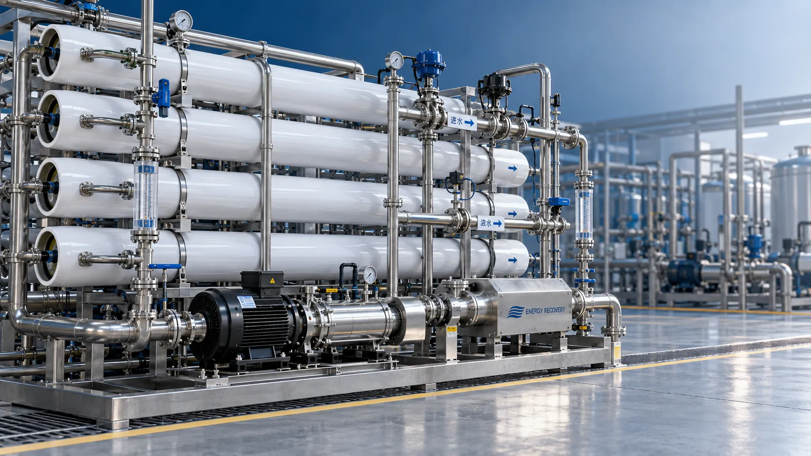
How to set recovery rates in seawater reverse osmosis system design
Explore seawater desalination systems engineering: learn to set SWRO recovery rates that balance energy, scaling risks, and water quality for reliable, cost-effective operation.
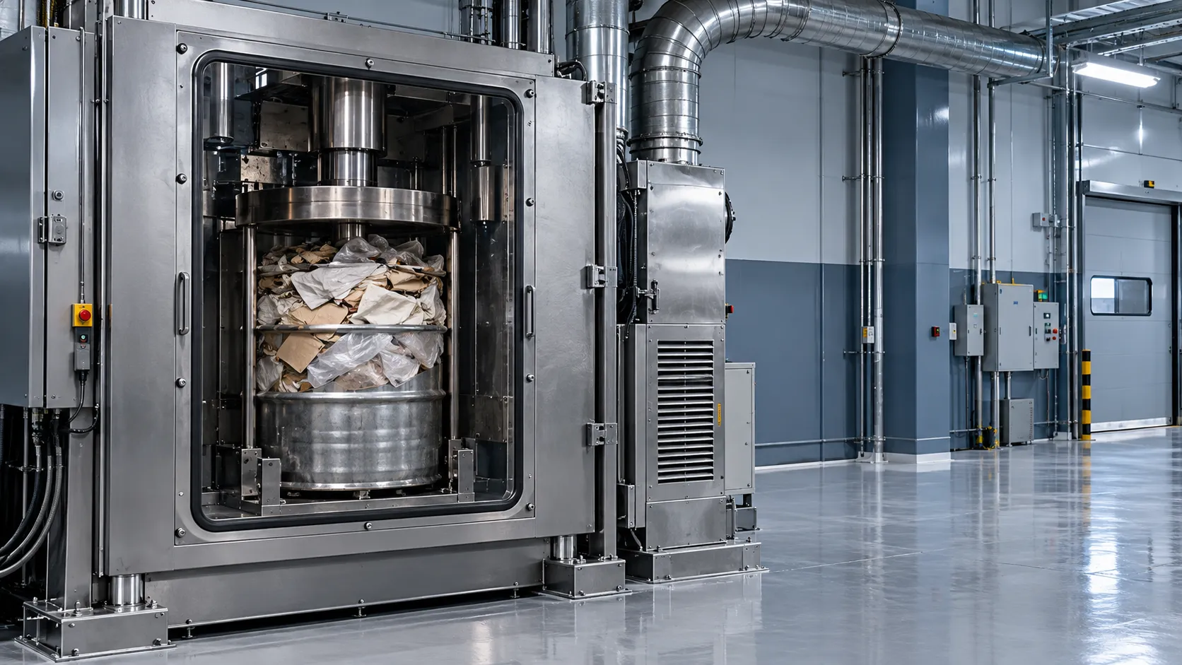
When is compaction suitable for solid nuclear waste treatment?
Is compaction right for solid nuclear waste treatment? Discover suitable waste streams, key safety checks, and disposal requirements to reduce package volume and optimize costs.
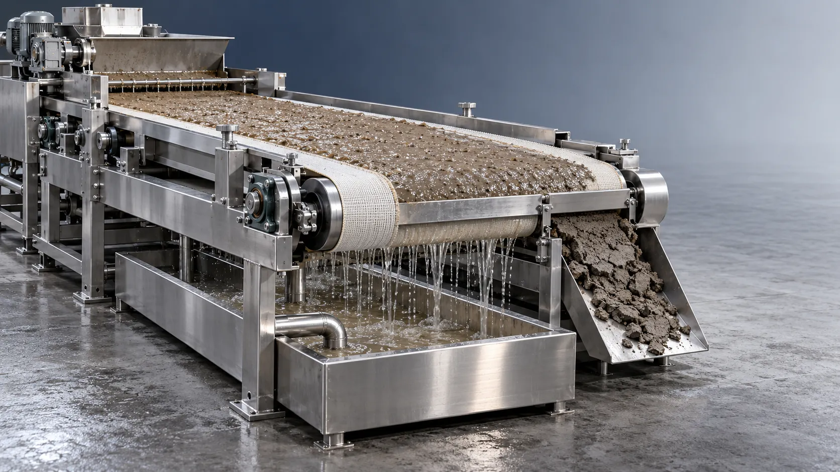
How solids concentration affects dewatering in waste recovery systems
Optimize waste recovery systems dewatering with insights on solids concentration. Learn to balance throughput, cake dryness, and solids capture while avoiding costly equipment overloads.
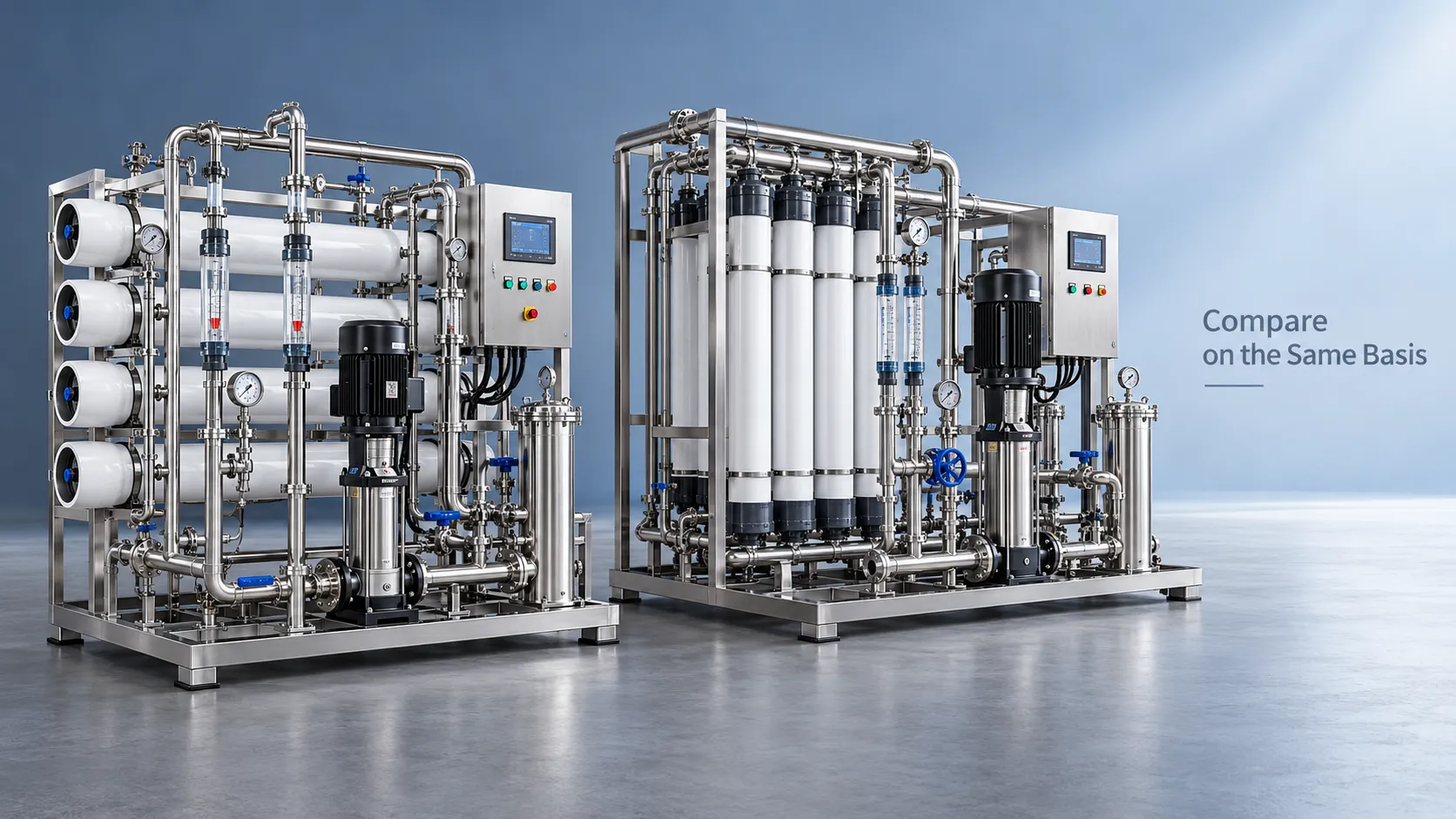
How to compare technical specs in an environmental equipment directory
Use this environmental equipment directory technical guide to compare capacity, energy use, compliance, and supplier evidence. Build a defensible shortlist and choose with confidence.
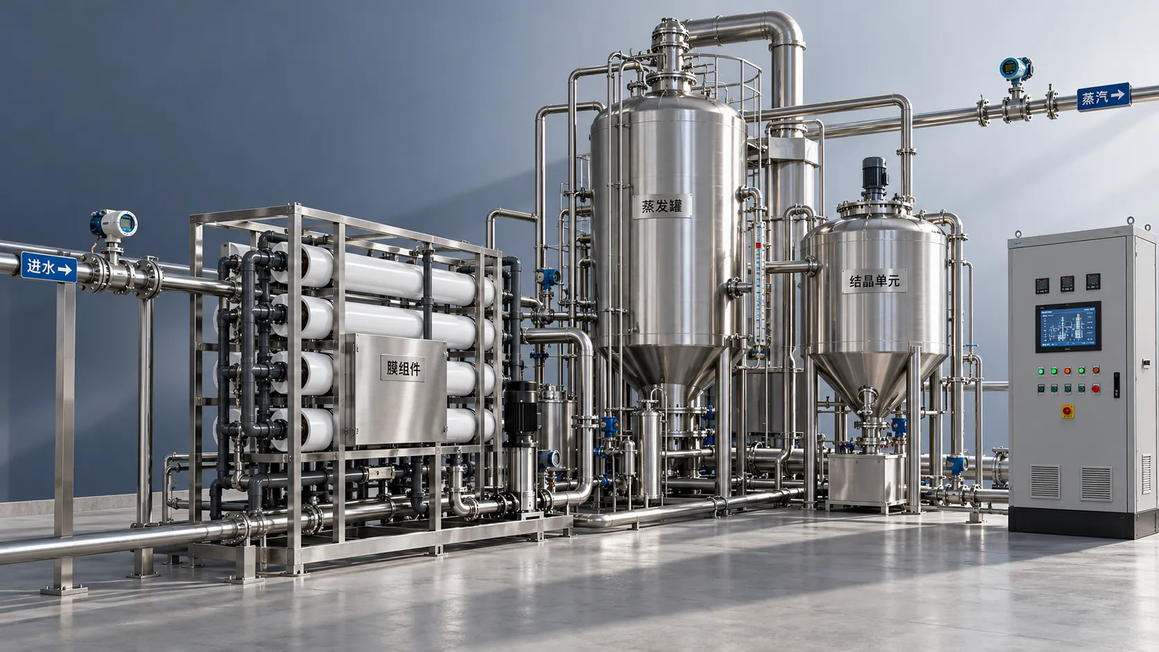
How to assess a zero liquid discharge equipment supplier’s energy claims
Assess a zero liquid discharge equipment supplier’s energy claims. Learn how to verify system boundaries, compare real costs, and demand testable guarantees before you buy.
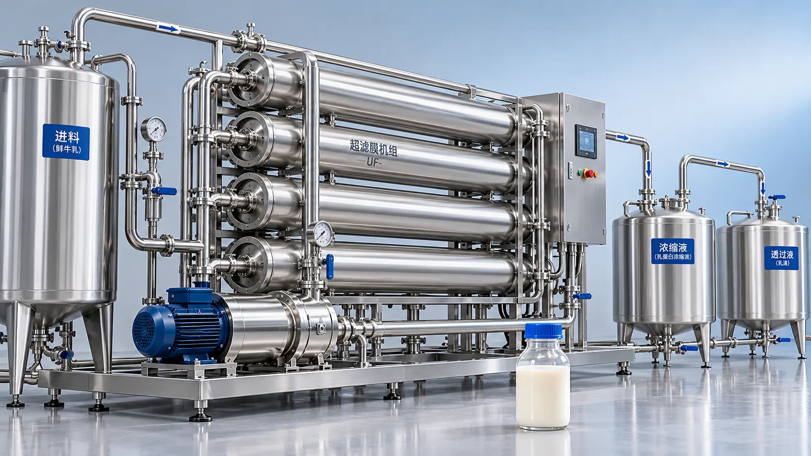
Which membrane filtration process suits dairy protein concentration?
Explore membrane filtration for dairy: compare UF, MF, and RO to select the right process for protein concentration, lactose reduction, and better recovery. Find your best fit.
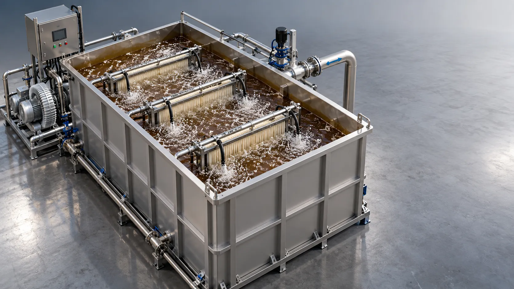
When is an MBR suitable for wastewater purification for bioprocessing?
For wastewater purification for bioprocessing, discover when an MBR fits your needs. Compare water quality, fouling risks, and lifecycle costs before investing.
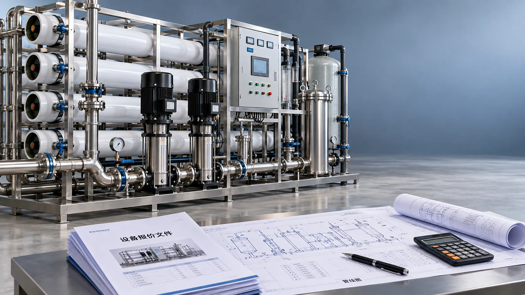
How to check a water treatment quotation for hidden project costs
Review your water treatment quotation for hidden costs, scope gaps, and operating expenses. Learn what to check before signing to protect your budget and avoid costly surprises.