
Industry News
Curation by industry experts
Hot Articles
Popular Tags
When high flux membrane water treatment justifies a larger footprint
A larger membrane footprint is justified when the apparent savings from a compact high-flux design are likely to be erased by unstable operation. High-flux elements can deliver substantial permeate production per vessel, but that output is achieved under a specific combination of feed quality, temperature, recovery, transmembrane pressure, and cleaning condition. When those conditions vary, designing close to the maximum flux limit leaves little room to protect membrane performance.
For difficult industrial wastewater, seasonal surface water, reuse applications, and desalination pretreatment trains with variable upstream performance, extra membrane area is often a resilience investment. It lowers the flux required to meet the design flow, reduces the rate at which concentration polarization develops at the membrane surface, and creates operating margin when feedwater quality degrades. The plant occupies more space, but the added area can reduce the frequency of chemically intensive recovery actions, avoid forced production reductions, and make future expansion less disruptive.
Start with operating flux, not the nominal output of an element
High-flux membrane water treatment is often evaluated from a product data sheet showing permeate flow under reference conditions. That figure is useful for comparing membrane families, yet it is not a design flux. Reference tests generally use controlled water chemistry, a stable temperature, and conditions that do not represent the suspended solids, organic load, scaling tendency, or biological activity of a real feed stream.
The relevant question is whether the required production rate can be sustained at a conservative flux after accounting for the poorest credible operating period. This period may be a warm-water season that increases biological activity, a cold-water period that reduces permeability, a wet-weather event that changes municipal influent characteristics, or a process upset that carries more oil, silica, hardness, or residual coagulant into pretreatment.
Designing with additional membrane area reduces the net flux per square metre. That change is meaningful because fouling is not proportional to flow in a simple linear way. Once local flux becomes high enough to concentrate rejected material at the membrane surface, a modest capacity target can produce a disproportionate decline in permeability. A compact train may then require higher feed pressure merely to hold the same permeate flow, even though the membrane itself has not reached the end of its useful life.
Extra area is particularly defensible when the feedwater contains components whose removal is imperfect upstream: fine colloids, emulsified oils, natural organic matter, polymer carryover, metal hydroxide particles, or biologically active nutrients. Pretreatment should control these hazards, but membrane sizing should not assume that every pretreatment barrier will remain at ideal performance throughout the operating cycle.
When a compact design becomes operationally expensive
A small footprint can be attractive where land is constrained, civil works are costly, or installation must fit an existing building. The risk arises when membrane loading is pushed upward to compensate for limited rack space. The resulting design may meet capacity during acceptance conditions while becoming difficult to control after the first period of feed variation.
Several field symptoms point to a design that is too compact for the duty:
- Feed pressure rises steadily between cleanings while permeate flow is held constant, suggesting that foulant resistance is accumulating faster than routine backwash or flushing can remove it.
- Permeate quality changes after recovery is increased, even though the average flux appears acceptable. This can indicate localized concentration effects or inadequate hydraulic distribution across the train.
- Cleaning intervals shorten after a change in upstream chemistry, such as a new coagulant, altered antiscalant program, production expansion, or different wastewater source.
- One stage or one rack loses performance faster than the rest. This often reflects uneven loading, dead zones, or a poor match between stage recovery and the actual feedwater fouling profile rather than a generic membrane problem.
- Production capacity can only be restored by increasing pressure close to equipment or membrane limits. That is a warning that the system has little remaining operating margin.
These symptoms should not automatically lead to a larger membrane system. A blocked cartridge filter, damaged media filtration, air entrainment, incorrect chemical dosing, or poor clean-in-place execution can create similar trends. The distinction matters. Adding membrane area will not correct a recurring upstream solids release or a hydraulically unbalanced skid. However, when the root cause is an inherently aggressive duty at a high normalized flux, added area directly reduces the driving force behind the problem.
Fouling control is a footprint decision
Membrane fouling is often discussed as a maintenance issue, but it begins as a hydraulic design choice. Higher flux draws water through the membrane more quickly and increases the concentration of retained material close to the surface. Crossflow helps sweep that material away, but crossflow velocity is limited by pressure drop, pumping energy, channel geometry, and element construction. A design that relies on unusually high crossflow to support a compact membrane area can exchange one problem for another: lower fouling at the cost of higher circulation energy and more demanding pump duty.
The dominant foulant should influence the decision. Colloidal fouling is sensitive to feed solids, floc carryover, and surface charge conditions. Organic fouling often becomes more persistent where hydrophobic compounds or soluble microbial products are present. Mineral scaling depends on concentration, pH, temperature, recovery, and the accuracy of chemical control. Biofouling is shaped by nutrient availability, stagnation zones, disinfection compatibility, and downtime. These mechanisms overlap, yet they do not respond equally to the same design changes.
For example, reducing flux may substantially slow organic and colloidal deposition, while a scaling-limited system may require lower recovery, better antiscalant control, pH adjustment, or an altered staging arrangement as well. A larger footprint should therefore be evaluated alongside feedwater analysis, saturation modelling, pretreatment performance history, and cleaning records. It is not a substitute for chemistry control.
More membrane area changes the cleaning burden
When membrane area is increased, each element generally operates at a lower production duty. This can extend the interval before a clean-in-place event is required and improve the chance that a cleaning solution removes foulant before it becomes strongly attached or chemically transformed. The benefit is not simply fewer cleaning events. It can also mean less production disruption, lower exposure of membranes to aggressive cleaning chemicals, and fewer opportunities for cleaning errors such as poor temperature control, insufficient circulation, incomplete rinsing, or incorrect chemical sequence.
There is a limit. A very large array introduces more housings, valves, instruments, connections, and potential isolation points. If cleaning circulation paths are poorly designed, the additional area may be unevenly cleaned. Rack layout must provide adequate flow through every train during cleaning, credible drainage, venting that prevents trapped air, and access for replacing elements without dismantling unrelated piping.
Energy performance must be assessed over the operating range
Higher-flux elements are frequently selected to reduce the number of pressure vessels and shorten the skid. Their energy outcome is less obvious. At a given feedwater condition, more area can achieve the required permeate rate at lower net driving pressure. That may lower feed-pump energy, particularly as membranes age or water temperature falls. In reverse osmosis and nanofiltration systems, lower flux may also support a recovery and staging arrangement that avoids excessive brine-side concentration in the final elements.
Yet a larger membrane field increases the volume of water inside housings and pipework, potentially increases recirculation requirements, and may add pressure drop through headers or manifolds. Energy comparison should use a process model that includes pump efficiency at expected turndown, pressure losses, recovery-control valves, temperature correction, membrane ageing allowance, and the energy associated with flushes and cleanings. Comparing only the initial specific energy at nominal production can favour a compact design that performs poorly after several months of service.
Feed temperature deserves particular attention. Cold water reduces membrane permeability, so systems designed tightly around warm or average conditions may need substantial pressure increases in winter. Conversely, warm feed may raise flux while worsening biological growth or scaling risk. Additional installed area gives control systems more room to handle these seasonal shifts without operating continuously at an extreme pressure or recovery setting.
Redundancy is useful only when it can be isolated and used
A larger footprint can provide genuine availability if the membrane trains are divided into independently isolable blocks. Spare installed area is valuable when one block can be cleaned, inspected, or repaired while the remaining blocks maintain an acceptable production rate. It is less valuable when a common pretreatment failure, shared chemical skid, single high-pressure pump, or undersized permeate header remains the limiting point.
Train segmentation should match the maintenance strategy. A single large rack may minimize equipment count but can turn a membrane replacement or cleaning event into a plant-wide interruption. Multiple smaller trains require more valves and control logic, but allow staged cleaning and make it easier to compare normalized performance between parallel units. The selected arrangement should consider the practical isolation of feed, concentrate, permeate, flush water, and cleaning connections rather than treating redundancy as an element-count calculation.
Layout, access, and replacement logistics affect the real footprint
Membrane area should not be counted only as skid length and width. The usable footprint includes access aisles, removal clearance for pressure vessels and elements, chemical storage, cleaning skids, sample points, cartridge-filter changeout space, lifting routes, drainage containment, and room for instrument calibration. A dense arrangement that technically fits inside a building can impose long outages when access equipment cannot reach the end caps or when vessels must be removed in sequence.
Element replacement also has a quality dimension. Wet membranes require controlled storage and handling. Incorrect orientation, damaged brine seals, contaminated interconnectors, or an incomplete post-installation flush can compromise performance immediately. A layout that gives maintenance crews room to inspect end adapters, lubricate seals with compatible materials, verify vessel cleanliness, and stage replacement elements reduces avoidable commissioning problems.
For retrofit projects, structural loading, floor drains, door widths, and crane paths can decide whether a larger footprint is feasible. The cost of modifying these constraints should be compared with the operational consequence of retaining an aggressively loaded compact rack. In some facilities, a distributed arrangement across available rooms is more practical than attempting to enlarge one central skid, provided hydraulic balancing and control architecture remain manageable.
Use normalized data to separate design limits from correctable faults
Before approving additional membrane area, establish a baseline using normalized permeate flow, differential pressure, salt passage or relevant permeate-quality indicators, recovery, feed conductivity, pH, temperature, and cleaning response. Raw flow alone is misleading because temperature and feed salinity alter apparent membrane output. Normalization does not eliminate uncertainty, but it shows whether the system is losing permeability, developing channel blockage, suffering reduced rejection, or simply reacting to changing feed conditions.
A useful review compares the expected end-of-run condition with the plant's available pressure, permitted recovery range, cleaning capacity, and minimum acceptable production. The model should include conservative membrane ageing and a realistic pretreatment upset scenario. If the design only meets its target when membranes are clean, feedwater is favourable, and every train is online, the footprint is probably too small for a dependable duty.
Conversely, more area is hard to justify where feed quality is consistently controlled, performance data demonstrate stable normalized operation at the selected flux, and production can tolerate a planned cleaning or short outage. The aim is not maximum membrane quantity. It is enough installed area to keep the plant within controllable hydraulic, chemical, and maintenance limits over its actual operating envelope.
The strongest rationale for a larger membrane footprint is therefore not a headline flux value. It is evidence that lower membrane loading preserves capacity when the feed, temperature, equipment condition, and maintenance schedule stop matching ideal design assumptions.
Recommended News
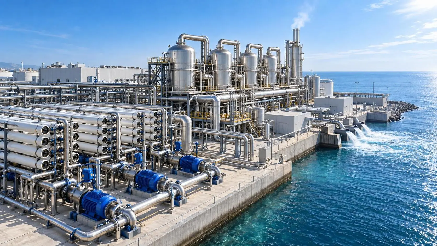
RO vs MED desalination: which is more energy-efficient at scale?
Desalination technology comparison: RO vs MED at scale. See how energy use, waste heat, feedwater, carbon, and flexibility determine the best choice.
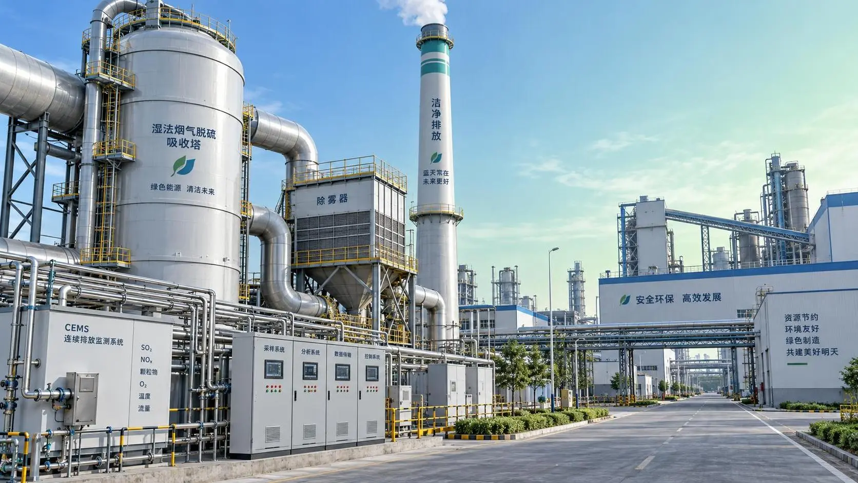
Which ISO standards apply to flue gas treatment systems?
Flue gas treatment systems ISO standards: explore key requirements for emissions testing, CEMS, safety, fabrication, corrosion control, and compliant project evaluation.

When corrosion resistant purification systems are needed for brine treatment
Corrosion resistant purification systems for brine treatment: assess chloride, heat, scaling, materials, and lifecycle reliability for demanding water projects.

How preventive maintenance reduces seawater desalination equipment downtime
Seawater desalination equipment maintenance reduces downtime through proactive monitoring, pretreatment protection, and planned repairs. Explore practical strategies for reliable RO performance.
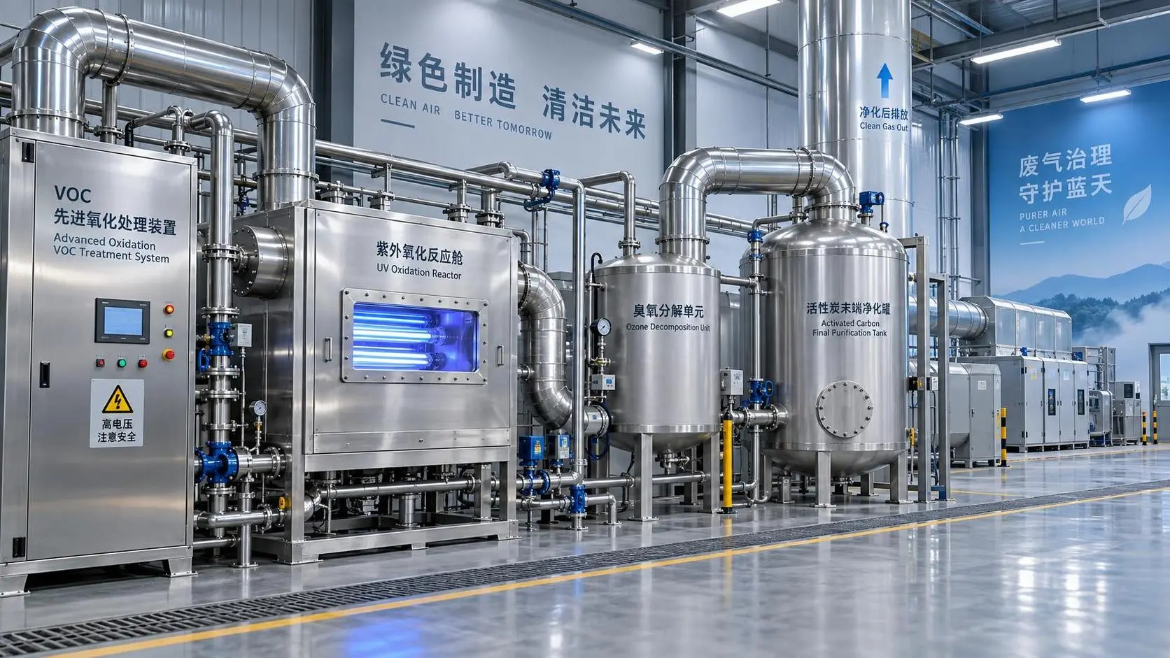
When are advanced oxidation processes the right choice for VOC control?
Advanced oxidation processes for VOC control: learn when AOPs outperform conventional options, manage by-products, and achieve reliable compliance.
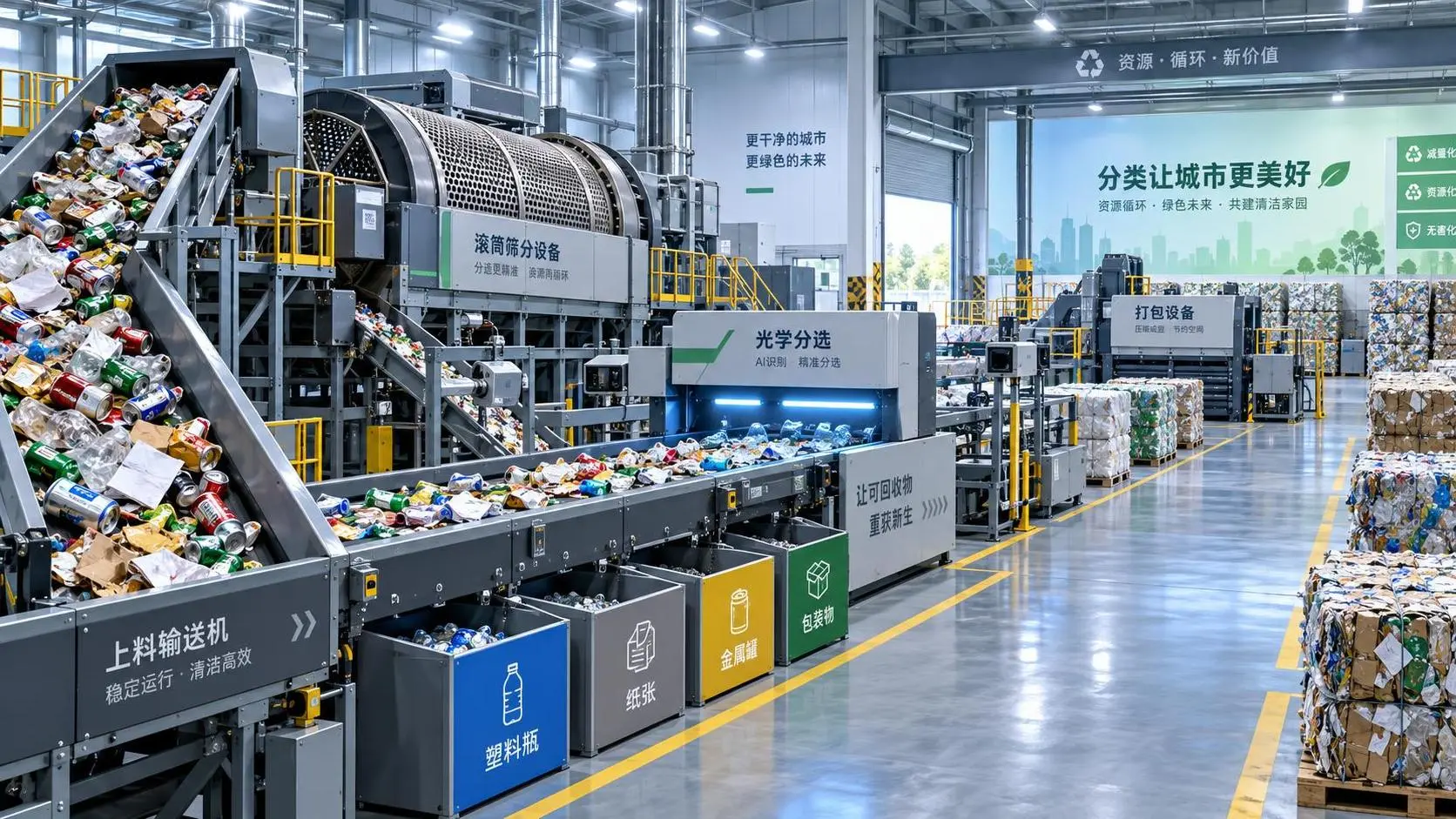
What throughput should municipal waste sorting equipment deliver?
Waste sorting equipment for municipal waste: learn how to set reliable throughput based on peak loads, material quality, uptime, and recovery targets.
What carbon neutrality means for corporate investment decisions
Carbon neutrality is transforming corporate investment decisions. Explore how lifecycle economics, efficiency, compliance, and resilience can drive measurable returns and lasting advantage.
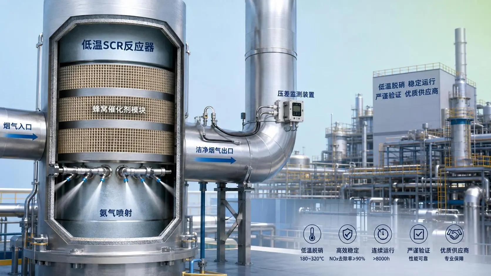
What to verify before choosing a low temperature SCR supplier
Low temperature SCR supplier checklist: verify catalyst temperature range, sulfur resistance, ammonia slip, pressure drop, lifecycle cost, and support before award.
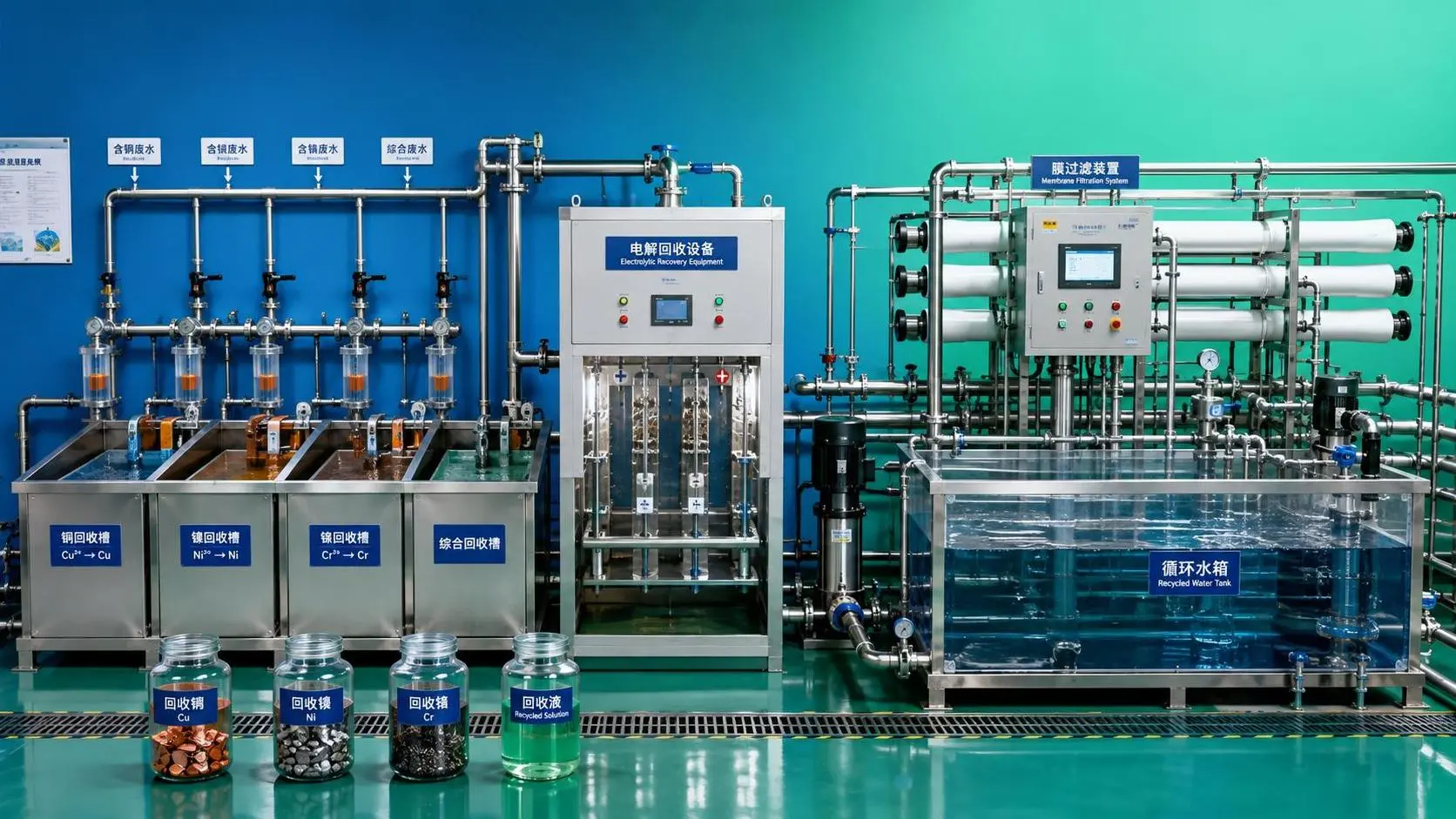
How closed-loop resource recovery for electroplating cuts metal waste
Closed-loop resource recovery for electroplating reduces metal waste, sludge, and water use through smarter stream segregation, recovery, and reuse strategies.